Differential pressure measuring and switching device (flow guards)

Differential pressure measuring and switching device (flow guards) for explosive areas which is suitable for differential pressure, overpressure and underpressure measurements in heat transfer oil systems and hot water systems. The operating principle of the system is identical in all three applications.

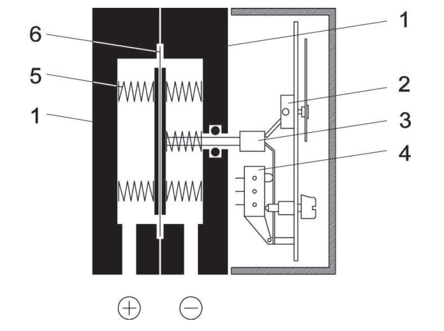
The flow guards comprise of a differental pressure transducer, e.g. measuring orifice, the differential pressure measuring ans switching device and corresponding shut-off fittings. 

  • High repeatability of switching points
  • Long service life
  • High overpressure protection
  • Structural testing

 Functional Scheme Differential pressure measuring and switching device flow guards

  1. Pressure chamber
  2. Motion train
  3. Tappet
  4. Micro-switches, operating elements
  5. Measuring springs
  6. Measuring membrane
General points:  
Measuring ranges: 0 ... 400 mbar to 0 ... 6 bar 
Rated pressure of the measuring system: 25 bar
Max. stat. operating pressure: depending on the measuring range (see order table)
Max. pressure load: one-sided over-pressure-proof up to the rated pressure of the measuring system resistance to under-pressure on the (+) and (-) side
approved temperatures for use in explosive areas  
Authorized ambient temperatures: -10°C ≤ Tamb ≤ 60°C
Max. approved medium temperature in the device: 60°C
Max. approved surface temperature: T70°C
Type of protection: IP 65 acc. to DIN EN 60529
Installation position: Pressure connections below
Measuring accuracy: ± 2.5 % of the upper range value
Zero-point adjustment: Arranged in the front panel of the scale
Switch points  
Contact output: 1 or 2 micro-switches, 1-pole changeover contact
Switch point setting: After opening and removing the bayonet ring, can be set to the reference csale via the front pane; smallest settable value approx. 5% of the end value of the measuring range
Switch point reproducibility: Corresponds to the measuring accuracy
Switch hysteresis: approx. 2.5% of the upper range value
Load data / contacts for use in explosive areas  

Highest values per electricity circuit:

Ui = 30 V 
Ii= 160 mA 
Pi= 800 mW
For use in explosive areas, devices must be connected to certified, intrinsically safe electricity circuits. Connections 1,2,3,4,5,6 in the cable connection soc ket. Internal capacity Ci and inductiveness Li are negligibly small.

Connections


Electrical connections

Cable connection socket

Pressure connection

Inner thread G 1/4, cutting ring screw connections pipes 6, 8, 10, 12 mm made of brass, steel or chr omium nickel steel Connection spigot G1/4 B DIN EN 837

Measuring system

Pressure spring measuring membrane system, membranes made of fabric-reinforced
Viton®

 Pressure chamber:

  • Aluminium GkAlSi10(Mg), painted black 

  • Aluminium GkAlSi10(Mg) with HART-COAT®-surface protection Chromium nickel steel 1.4305

Measuring membrane:

  • Measuring membrane and seals made of Viton®

Inner parts in contact with mediums:

  • Stainless steel 1.4310, 1.4305

Casing/bayonet ring:

  • 1.4301

Front pane:

  • Safety laminated glass

Weight:

  • Pressure chamber in Al = 1.2 kg, Pressure chamber in 1.4305 = 3.5 kg
Ask about this product